

GD32F130G6U6TR Specs & Pinout: Comprehensive Data Report
The GD32F130G6U6TR is a high-performance, compact 28-pin Cortex-M3 microcontroller designed for entry-level embedded control and IoT endpoints. This engineering reference verifies technical claims for PCB prototyping and production verification.
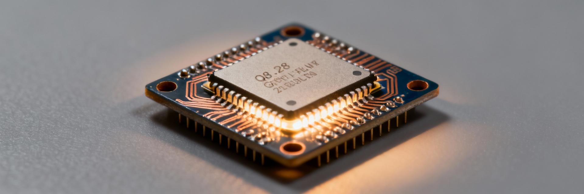
Overview & At-a-Glance Specs
Market Positioning
Point: The device is a value entry-level Cortex-M3 MCU suited for sensor nodes and simple control tasks.
Evidence: Official datasheet lists a single-core 32-bit pipeline and a modest peripheral mix.
Explanation: Designers choose this class when flash/RAM and pin count dominate cost and board-size constraints; compare on flash, SRAM, and available UART/SPI channels when selecting alternatives.
Performance Metrics
| Item | Specification (datasheet reference) |
|---|---|
| Core | 32-bit Cortex-M3 class, single core |
| Max CPU frequency | up to 48–72 MHz — verify in official datasheet |
| Flash | 64 KB typical (device family variants may differ) |
| SRAM | 8–20 KB depending on variant |
| Package | QFN-28, exposed pad |
Technical Specifications Breakdown
CPU, Clock Domains and Performance Metrics
Point: Clock behavior determines performance and power. Evidence: The datasheet details an internal PLL, multiple clock sources, and startup/reset clock paths. Explanation: Typical configurations place the core between 48 and 72 MHz using PLL from an internal or external oscillator; designers should implement a stable crystal and validate cycles-per-instruction.
Memory and Non-volatile Features
Flash and SRAM organization affects boot and update strategies. Official documentation specifies flash sectors, write/erase granularity, and available boot modes. Implement bootloader partitioning only after confirming sector sizes and recommended erase cycles.
Pinout & Package Details
| Pin # | Name | Primary Function | Alt Functions / Notes |
|---|---|---|---|
| 1 | VDD | Supply | Decouple close to pin |
| 2 | VSS | Ground | Exposed pad solder to ground plane |
| 3 | PA0 | GPIO / ADC_IN0 | ADC channel, external interrupt |
| 4 | PA1 | GPIO / USART_TX | Alternate USART or SPI functions |
Design Checklist & Reference Circuit
- 01 Decoupling: 0.1 μF + 1 μF close to VDD; place bulk cap on board input.
- 02 Reset: NRST pull-up 10 kΩ; add capacitor for brown-out filtering.
- 03 Clock: Keep crystal traces short; follow board stack recommendations.
- 04 Thermal/Pad: Solder mask openings for exposed pad and thermal vias.
Key Summary
Common Questions & Answers
What are the recommended power decoupling practices? +
How should the reset and boot pins be handled? +
What troubleshooting steps help when the MCU fails to boot? +
